LeSving wrote:
I haven’t seen a picture of these cracks yet though.
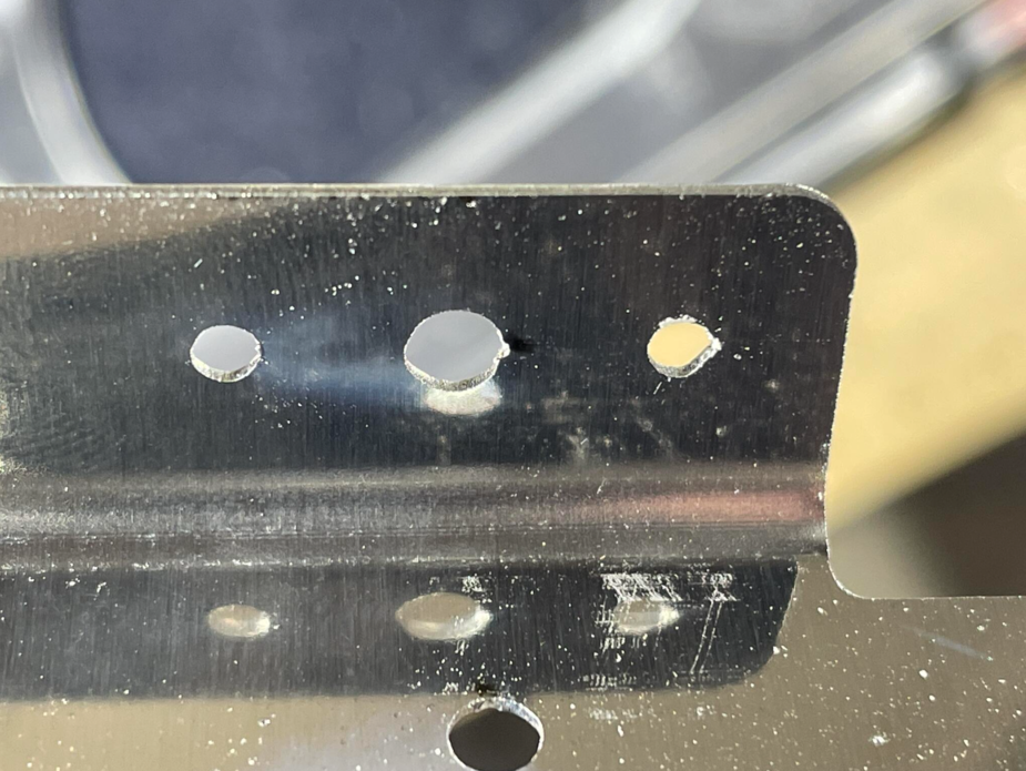
From VAF, here’s one that cracked on being dimpled:

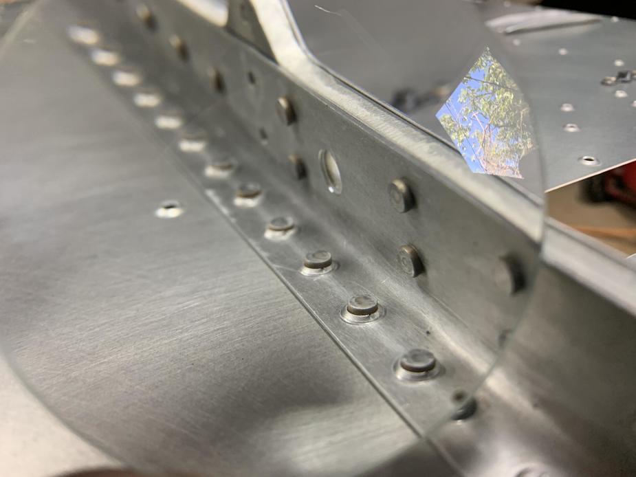
And these didn’t crack on dimpling, but did upon being riveted:
Graham wrote:
My priming (2x etch primer and 2x clear lacquer) adds about 1 thou in total, not per coat.
Yes I understand, and it sounds about spot on. 1 thousand of an inch is 24.5 micrometer. One coating of etch primer is about 10 micrometer. Theoretically it could be smaller, perhaps even less than 5, but in practice that is really hard to achieve and at the same time cover everything because the mist coming out isn’t fine enough, not from rattle cans or low pressure equipment. It also depends on the primer. High VOC is good in this respect. Lastly it depends on how much time you want to use on priming, which usually is not all that much 
The thing is though, it’s the mating surfaces that “need” primer. A member with flanges sandwiched in between two sheets for instance will therefore have 4 surfaces stacked on top of each other, each of them “need” primer. So, 1 + 1 + 1 + 1 = 4, or four thousands of an inch, which is 80% of five thousands of an inch, which is the difference in skin thickness. The typical overall accuracy to aim for is 1/16 of an inch = 1.5 mm (1500 micrometer). IMO that difference in sheet thickness is nothing to worry about, not when the “wrong” one is thicker (stronger). A human hair is 40-100 micrometer in diameter (0.0015 to 0.004 inches) in comparison.
Dan wrote:
a 5" use of the search machine would do it, but happy to serve you
Pease decipher.
Graham wrote:
From VAF, here’s one that cracked on being dimpled:
Thanks. The first picture I don’t understand. What are the two holes on each side? To install a nutplate ? It looks like the dimpling is done the wrong way in that case, or is it the picture? The dimple comes out of the picture, yes? The dimpled hole is also seriously big, way to big for structural stuff (which it isn’t, if it’s for a plate nut)
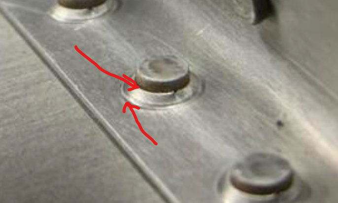
In the last picture the dimpling looks really goofy, like it has been double dimpled or something, and with the wrong tool the first time. It also looks like too short rivets have been used. Could be the picture, but what has been going on with the second dimple?
I don’t know. A hard time indeed for Van’s. And some people taking advantage of it perhaps? I have never seen such cracks though, but I have never seen such goofy dimpling either
@LeSving you can keep arguing your point about the paint but it won’t make any difference to anything. It doesn’t matter what you say about what can and cannot be achieved in terms of thin layers, my measuring of my own parts tells me that four coats (two of etch primer, two of lacquer) adds about a thou. Your mileage may vary.
If a part sandwiched between others is 5 thou thicker than it should be, everything that depends on it will be out by 5 thou. The paint makes no difference to anything, so long as either everything is painted or nothing is painted.
If I only aimed for accuracy of 1/16th then I’d have a right mess of an aeroplane that my inspector wouldn’t sign off. Edge distances would be compromised and plenty of stuff just wouldn’t line up well enough to be riveted together without seriously oval holes. As I said before, I’m not interested in whether the wrong part might work, I’m interested in the supplier having good enough QC to send me the right part in the first place.
The first picture is for a number 8 screw or something. Yes the holes at the side are for a nut plate. Perfectly normal. The second picture has particularly crisp dimpling, I will admit. The rivets are probably perfectly long enough – I will wager that the driven head diameter meets spec and the driven head height certainly does. When you’ve been doing loads you no longer need the gauge and can tell from the proportions. The minimum driven head diameter in the mil spec is really quite small, nothing like as much as the 1.5x shank diameter rule of thumb.
and another picture showing the extent of the problem…
Graham wrote:
As I said before, I’m not interested in whether the wrong part might work, I’m interested in the supplier having good enough QC to send me the right part in the first place.
Well mister Graham. The obvious question is. With your experience with Van’s, this particular episode, do you really think they have good enough QA (good enough to your liking) ?
I for sure don’t think they have (to my liking). They have never had it. I would never have bought a QB from them for instance, for this and other reasons (internal priming is the major one, and simply poor jobs as found by others). I only have experience with the -4, and the -4 is not as much a kit as it is a collection of barely fabricated pieces of metal. Sonex also offer kits in various degree of completion, all the way from plans built to QB kits. I wouldn’t hesitate at all to buy a quick built from them. This is mostly because their design philosophy and choices of structure and fasteners simply makes it impossible to not make a structurally sound aircraft, by anyone, and they use 6061 which is corrosion proof (more or less).
This doesn’t mean I’m right. Quite the opposite. I’m most certainly 100% wrong, as there are ton’s of RVs flying, and all of them seem to be doing OK from a structural point of view. I can only conclude that my personal level of what QA shall be is several notches above what Van’s can offer. I’m probably too pedantic. I had the impression that the newer kits were more IKEA style, don’t think, follow the manual kind of thing, but they obviously aren’t. Each builder has to assess the integrity of every piece to his liking there as well, and do some amount of thinking. That’s also how it has to be.
Graham wrote:
If I only aimed for accuracy of 1/16th then I’d have a right mess of an aeroplane that my inspector wouldn’t sign off. Edge distances would be compromised and plenty of stuff just wouldn’t line up well enough to be riveted together without seriously oval holes
That obviously was not what I meant by “typical overall accuracy” What I meant was 5 thousands of an inch difference – no one cares…
Graham wrote:
Yes the holes at the side are for a nut plate
What kind of nut plate is that? I’m seriously curios. Is it for some fast open/lock click kind of bolt?
Looking at the second picture again. The crack appears to be protruding inward towards the rivet. Which is physically odd. Someone is obviously trying to take advantage here IMO.
No, the crack comes outwards from the hole perimeter into the surrounding material.
I also wouldn’t buy a QB. Too many bad stories with the quality of build, including from someone personally known to me.
I’m disappointed with the level of QC. That said, I’m the builder and I take responsibility for ensuring something is to my satisfaction before it becomes part of the aeroplane. But its more a pain in the ass than dangerous, because its delaying my build. Perhaps my standards are unreasonable.
Graham wrote:
Perhaps my standards are unreasonable.
I think it’s unreasonable to expect others to adhere to “your” standard when there is no universally accepted standard in the first place. That’s the reason we have tons and tons of industry standards: clear cut definitions of what everyone should expect. For experimental aircraft (homebuilt), there is no standard. At best there is “best practice” manuals that the builder can use. Even ULs are built after standards (of some sort) depending on country of manufacturing (and the country it is sold). For a homebuilt aircraft, the only thing of importance is airworthiness. For a kit this is usually assured by the kit manufacturer designing and testing as best as they can (which usually include prototypes and several beta builders), then the builder follows best practice manuals during building together with QA by some “knowledgeable dude/dudess”, and final flight testing.
There is nothing wrong with laser cutting. But, laser cutting rivet holes all the way up to the final diameter? Is that even physically possible without adverse effect due to heating, and some raggedness in the cut? I wouldn’t think so, but don’t know for sure. It certainly is not according to any “best practice” manual I have read (which usually are from the 50s-60s anyway regarding metal work). Is punched rivet holes up to final diameter according to any best practice manual? The best practice manual I have read say that a rivet hole shall be cut to final dimension by a drill or reamer to not induce stresses in the material edges, then slightly deburr. The major difference here is that induces stresses are invisible and the hole looks nice when punching, while laser cut holes does not look equally nice. I thing to remember is that kit manufacturers aren’t bound by best practice and so on. If they were, they would be making Piper Cubs exclusively (which some do, and call it Carbon Cub )
Then when Van’s say they have done fatigue tests of laser cut parts. What exactly is the big deal? Those pictures above mostly shows severely odd dimple work. Those ragged holes does not look nice, but a big deal to fix? perhaps, perhaps not, mostly dependent on if it’s a one off or a 1000 off
Is this rivet long enough, particularly given the material around it has cracked?
It looks a bit flat in its final height, though looks can be deceiving.
The building standards, which are also used in the homebuilt airplane manufacturing process, require a 1/2 o of the rivet’s o in height, and 1 1/2 in width, after squeezing/pounding.
In most countries a tech advisor, or building advisor, is delegated by the relevant homebuider association, in a mentor and supervisory role, and should have all sub-standard practices corrected. And so should the country’s NAA before issuing a PtF…
In this very case the hole dimple cracked, or was already cracked, and then split, thereby allowing the rivet to set flatter than it should.
When I built the RV-4, I only used a rivet gage for the first 10’000 or so rivets… no need for the gage for the next 10’000 
The military specification is that a 3/32 rivet (an ‘AD3’ rivet in the AN nomenclature) should have a minimum driven head diameter of 0.122" and a driven head thickness between 0.038" and 0.050". For simplicity, this tends to get rounded up the rules of thumb that @Dan mentions.
I would wager that the examples shown in the photographs meet the specification. One cannot be 100% sure without measuring it, but my experience is that it has to be barely driven at all to fail on minimum diameter and squashed very flat indeed to fail on minimum thickness.
I find it is more common to fail on maximum thickness because the kit manufacturer has specified too long a rivet. One can often go down one rivet length from that called out in the plans and still meet spec, and although I try not to do this unless I have to it can be useful in a tricky location where a longer rivet tends to tip over while being set.
@LeSving I don’t think there’s anything particularly odd about the dimples, although they do look really crisp. I’m not sure what you’re seeing, but my take is that the guy used springback dies and hit them very hard. The part does look on the thick side for dimpling (as opposed to countersinking).