
The Field Wire is really hard to see, it runs through those black plastic hoses on the front of the Firewall and since I have air condition there’s a lot of stuff in that area .. and it would take hours to open all that up.
If I disconnect both sides, how do i measure the wire? How is that done correctly?
My plan for now is:
- Check alternator has no short
- check the wire
- install new FCM/Voltage regulator
You agree?
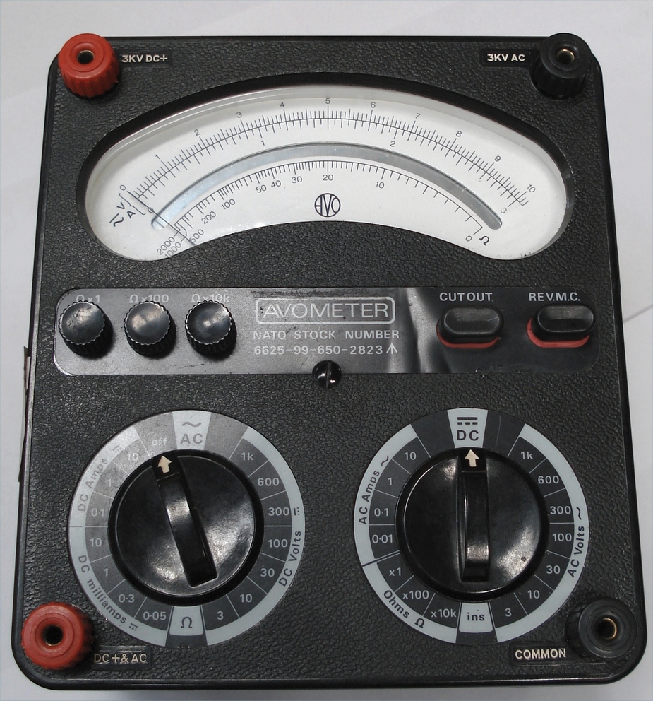
You need one of these

on the ohms range.
Yes :-)
I am really a layman when it’s about electrics/electronics. What does it have to show? I’ll do that with the service center anyway, but now I’d like to learn it myself
Peter wrote:
so the other end of the regulator feeds the field winding, and the other end of the field winding is grounded in the alternator?
Yes. The regulator itself isn’t drawn in the schematic, it isn’t buss voltage on the field, a bit simplistic schematic. For now there is definitely something wrong other the the alternator. The alternator might be failed as well, but there must be another failure on wiring or regulator.
Isn’t the regulator the box called VOLT REG?
The simplest regulator needs 3 wires
A multimeter on the ohms range will read some fraction of an ohm, for a piece of wire. Usually it reads that much just due to the resistance of its test leads.
Peter wrote:
Isn’t the regulator the box called VOLT REG?The simplest regulator needs 3 wires
Correct. That is why I refered to it as being a bit simplistic. It doesn’t show all wiring, and neglects all grounds on the alternator regulator and alternator itself. I hate these schematics where some items are left out. It doesn’t help in giving a better understanding.
Forget this digital nonsense, for fault finding you can’t beat one of these. The moving coil is the gold standard!
Cirrus must publish proper wiring diagrams, like e.g. this corresponding one for mine

It took me years to get hold of this stuff.
The above came out of the Feb 2006 ATP MM (briefly sold on Ebay till the vendor got busted – the last Socata change was in 2005) and I would expect Cirrus do the same i.e. sell the reproduction license for their MM to ATP who then sell monthly-update subscription packages to maint companies for c. $1000/year. So I would try to get hold of one of the monthly CDs – they are supposed to be binned when each update arrives. These are priceless in case you have to use a “smaller” company for maintenance; most of those don’t pay the monthly subs because it is the $1000/year per aircraft type which obviously gets ridiculous, so one has to be, ahem, realistic…
In reality, for a given “old” aircraft, 99.9% of th CD contents doesn’t change from one CD to the next. The monthly update is a legal facade.
But beware – Cirrus may not have supplied all wiring details to ATP. Socata didn’t supply any wiring diagrams updated after ~ year 2000 i.e. anything GT-specific. The GT wiring lives in PDFs which exist separately (which I have too, due to having some good friends in low places  ).
).
Anyway, an owner needs to get all this stuff.
Forget this digital nonsense, for fault finding you can’t beat one of these. The moving coil is the gold standard!
Back in CZ, only the head of the Comm Party could get an AVO. I didn’t get a multimeter until we escaped to the UK and then I got this one for 10 shillings.
Neil wrote:
The moving coil is the gold standard!
Totally agree on that, one should have at least one analog meter as well.
Peter wrote:
So I would try to get hold of one of the monthly CDs
I don’t think they are used that much, it seems online is standard nowadays. Licenses are very expensive IMHO, especially if you see the quality of the old scanned manuals.
There’s an extra WIRING MANUAL, I just found that, and it contains detailled drawings of every electrical system and subsystem and for every version of the plane ever produced.
You can have a look online if it interests you:
http://servicecenters.cirrusdesign.com/techpubs/pdf/WM/SR22/html/wmtoc.html
I just ordered the Field Control Module (Voltage Regulator). It was around € 180, so it’s not that bad


