ok thanks guys
so if I understand it correct I have to:
1) insulate the headphone jacks with an insulated flat washer and shoulder washer
2) use 1 wire shielded cable, starting from pin 9 (pilot headphone) and connect the shield of this cable with the ground of the intercom(pin1)
connect the wire to the tip of the headphone jack and the shield to the sleeve of this jack
3) do the same for the copilot headphone jack (pin 11)
I am thinking ….. could I do the same for the PTTswitches???
I will change the diagram and post an update asap
once again thanks for all info and ideas
greets Danny
Your picture is too small to make out the details, such as pin numbers. Perhaps you could post a bigger image at some picture sharing service? That said:
1) perhaps, but probably not required. If you have a metal dashboard (or other carrier for the headphone plugs, perhaps a small aluminium box or so) just mount the headphone jacks on there. If an insulated installation is really required you can replace some of the dashboard real estate with a bit of plastic or polysester sheet; or replace the alu box with a plastic one. Or yould use plastic/nylon jack sockets; though these will not be easily found for the exotic size of the microphone plugs.
2+3) yes, correct. If mounting the jacks onto conductive and earthed sheet, it may be better to not connect the shielding braid at one end – experiment to find which one.
4) PTT: yes, you could; it is done like that for the PTT switches in my own bird, though with “consumer grade” shielded cable.
You can go up to 925 pixels wide using the drag/drop here.
Any wider and it will be scaled down to 925px for the browser.
So for the very best result, scale any image to 925px using your image editor.
hopefully this is better will see
Ohhh… i forgot to connect the tip of the emergency microphone as PTT. As Jesse said…
Hehe, thanks for your efforts. Allow me to suggest:
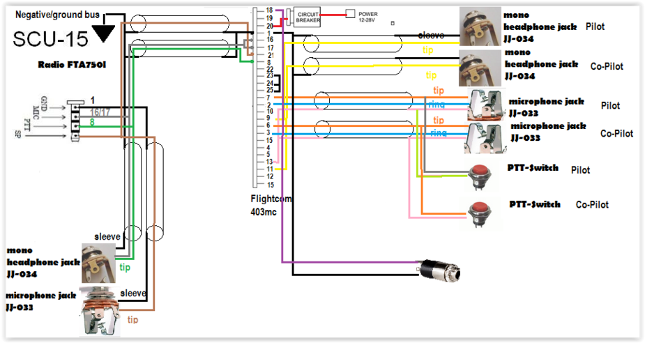
-) there is now shielded wire for the headphone jacks, as per Jesse’s recommendation. It is not a prime requirement but it won’t hurt
-) there is however no shielded wire where it is really needed: on the microphone connections. Add that shielding! Three times!
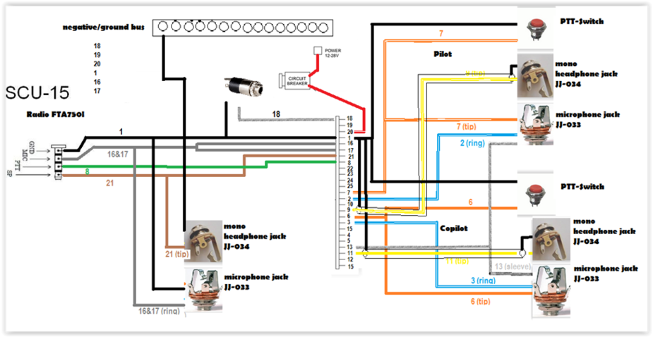
-) a bit unclear what you intend to do with the ground wires; I suggest the wire from your ground bus goes straight to the intercom, pin 1 (see below)
-) what is/does the grey wire from the intercom pin 18? what is the component it leads to? [[ edit: seems to be an aux input for a CD player or so. Do you really want that? But you could perhaps use it for audible alarms from a GPS unit, if you are about to enter some forbidden airspace or so.]]
-) pin 1 is “power ground” and 13 is “signal ground” The shield braids should go to 13, rather than to the power ground as shown; so should all the jacks’ sleeve contacts, too. The ground to the PTT switches is less critical, but the circuit shows them on the “power” ground i.e. pin 1, as you plan
-) if the radio allows it, consider adding a power cable for it. Power FROM the circuit breaker or intercom pin 20 TO a suitable plug, ground to the same from pin 1 or from the “ground bus bar”.
-) if you are not sufficiently confused yet: I seem to remember a circuit with a relay that commutes the pilot’s headphone between the intercom (normal operation) and the com radio (emergency, if the intercom gives up). Would have to scratch my head, though. Perhaps Peter has something in his archive. Applying such a scheme would save you the third set of jack sockets.
hello Jan Olie…….
i am going to respond in parts beginning at the end
the flightcom 403mc has a buildin relay for an emergency if the intercom is broken
so no headage over that pfffff…
yes the radio has a 12v cigarette/car charger. but i guess it has nothing to do with the intercom harness
about pin 13 and the microphone wire shielding i think you are correct
i have to use a shielded wire
think i gonna use a 2 wire shielded cable
connect pin 13 to the shield and at the other end to the sleeve of the pilot microphone jack
than connect pin 2 to one of the wires of the shielded cable and connect it to the ring of the pilot microjack
than connect pin 7 to the other wire and connect it to the tip of the pilot microjack
and do the same for the copilot mike
if i look at the diagram on the first page of this topic it shows that only the mike jacks are connected to pin 13
as the ptt switches and headphone jacks are just grounded i think to pin 1
Let me know how cutting the cables from the SC15 connector goes. I’m toying with the idea of doing the same for mine – if not to connect an intercom, then to connect the PTT switch, and possibly the headset, directly.
I’ve had some odd experiences in the past doing this with headphones – wires that won’t take solder (not just plain enamelled) for example.
hello kwlf
maybe its good to keep the scu-15 complete and make a extension cable with to male acks that you plug into the scu-15 and on the other end 2 female jacks and the ptt as standalone
think i gonna do it like that its maybe the cleannest way
greets Danny
think this is spot on
Scratch wrote:
think this is spot on
Looks good, you only switched the text and photo at the left hand (emergency) audio connectors.