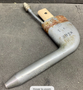
Following my Italian adventure I have been looking for replacements. Perhaps the most common heated type is the AN5812
These list from $2122.00 to $4146.00 for 24V (5812-1) and 12V (5812-12) respectively (that’s strange too).
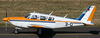
They come up on Ebay at silly-low prices if you don’t need paperwork (true for N-reg; possible under EASA depending on interpretation) e.g. 45 quid for this:
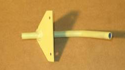
The funny thing is that when you go to an avionics shop to get the pitot/static test done, they don’t blow air at the pitot tube. They just connect a hose to it and pressurise it statically. This suggests that any forward facing tube will produce the same pressure; a pitot from an F16 fitted to a TB20 would read the same airspeed (presumably only at subsonic speeds) as the 5812. And indeed Socata lists this contraption for €90; apparently the right part for very old TBs, but it is used with a bog standard ASI instrument
Is that really true?
Peter wrote:
Is that really true?
No! Sort of true, but the exact position on the aircraft matters, sometimes a lot. With position I mean where the tip is relative to the aircraft structure. The shape of the pitot tube matters also, but less so than changing placement on the aircraft. If you want identical measurements (without calibrating), you need to replace the pitot tube with an exact replica at the exact same place on the aircraft. There is also the static port. This can vary from aircraft and pitot. Some have the static on the pitot tube. This is really the only thing that can be called a “real” pitot tube. Others have it on the fuselage.
Does it matter? It matters if you want the same (erroneous) readings as before, which probably is important for a certified aircraft. Particularly at low speed/high AoA the reading is all wrong. With an AoA indicator this can be corrected in the flight computer 
From physics principles I would expect the same pressure indication for any tube (probe) installed at the same spot.
Differences in diameter of the probe might be important for supplying the same value for a different number of gauges installed in the panel. So a small pitot tube might be limited in the number of instruments connected (due to possible counterpressure of the instruments)
And also a bigger tube might suffer less from boundary effects (not the boundary of the airflow around the airfoil, but the boundary of the surrounding casing of the probe)
However, there are more effects to be taken into account, like a tendency to get iced up and the effectiveness of pitot heating. But in principle, the diameter of the tube, should in the first order, not affect the indication.
I have lots of literature at work about pitot tubes. Don’t remember the specifics, but in general:
For practical use, as in an aircraft, the most important aspect is perhaps it’s NOT a precision instrument. It gives an indication of speed, but with large errors. The most important thing is therefore it is not blocked and it is not leaking. To be more precise: Consistent and repetitive reading is perhaps assured with 99.99% certainty as long as it is not blocked and/or not leaking.
So a small pitot tube might be limited in the number of instruments connected (due to possible counterpressure of the instruments)
I get your drift but I don’t think it matters, because under steady state conditions there is zero flow rate. The pressure is created at the pitot entrance and will propagate to every part of the pipework. If it didn’t, a connection of e.g. a second altimeter or an autopilot, ADC, etc, would affect everything.
it’s NOT a precision instrument
I fully agree, but I think that all altimeters “we” use are equally inaccurate. Otherwise, the GA business, with its standardised instruments, would not be able to exist. Every instrument with an IAS input would need to specify a pitot tube model. Yet none of them do. They must all conform to some standard curve. Probably something worked out in 1940 and no longer found on google
The position of the pitot will obviously matter to some extent, hence the IAS-CAS corrections in the POH. The correction usually gets bigger as the AoA increases, which would be expected.
Peter wrote:
Every instrument with an IAS input would need to specify a pitot tube model. Yet none of them do. They must all conform to some standard curve. Probably something worked out in 1940 and no longer found on google
They don’t because – as you say – there is a difference between IAS and CAS and we accept that. Any pressure change created by the pitot tube contributes to that difference. (Also, of course the location for the the pitot tube matters.)
The correction is tiny though.
Peter wrote:
The correction is tiny though.
That depends on the airspeed (or AoA mostly, at least for low Mach numbers). The instruments themselves are all calibrated after standard atmosphere. I have no idea how this is for a B-737 for instance. There is no reason the IAS should not be very much like CAS on those due to possibilities of correcting it in real time.
Another thing, how would you know how off the IAS actually is? In an experimental aircraft you can (must/should) do it as part of the test procedure. I read about it years ago (I think that was EAA), but the same procedure can be found in Kitplanes here and here. This is also useful here.
I think it is fairly obvious that the way the pitot system must be highly performance-standardised, otherwise we would not have the big GA business in altimeters and pitot tubes of all kinds. They would not be interoperable.
Sure; my ASI has been calibrated; several methods (various threads, and mentioned in the above Kitplanes link). Simplest is the 3 × 120deg method which yields TAS and you correct it back. Someone will now point out that gives you IAS not CAS but that is a trivial difference at cruise speeds.
A 737 will be a very different thing due to compressibility.
It’s been pointed out to me that a pitot tube measures dynamic pressure + static pressure. Well, of course, but the argument is the same. This is why an ASI has both pitot and static tubes going into the back of it.
Only the indicator, the instrument in the cockpit or the dP transducer, is standardized AFAIK.
In principle all total pressure tubes will measure the same, as long as they are mounted straight into the velocity vector of the air and some distance outside the boundary layers and away from other disturbances. The same cannot be said for the static pressure. It must be mounted perpendicular to the flow, but it is not irrelevant where you mount it. Mounting it on top of the wing is fairly stupid for instance. It could be in the tube itself, but then the position of the tube is not “irrelevant” anymore, and neither is the tube.
Peter wrote:
A 737 will be a very different thing due to compressibility.
That makes no difference, only different calculations that also works for low Mach numbers (thinking digital, not analogue).
Anyway, this NASA report explains all of what pilots need to know about the subject
This report answers most of what you are asking: