Peter wrote:
Sure; the TAS → IAS conversion is trivial.
TAS → CAS conversion is trivial. To IAS less so. You will have to trust the POH airspeed calibration data.
Peter wrote:
Splitting hairs
Not really. A 5 knot difference at cruise speed would not be surprising.
It is splitting hairs in this context because the IAS-CAS correction is driven by airframe geometry / pitot tube location, so is a fixed value for a given aircraft design.
It is perfectly OK to calculate TAS and then back-calculate IAS from that, and one takes care of instrument indication errors.
Peter wrote:
is a fixed value for a given aircraft design.
It is actually not. It varies with airspeed. In any case, if you want to calibrate your ASI with the 3xGS method you must take the IAS-CAS difference into account.
Airborne_Again wrote:
In any case, if you want to calibrate your ASI with the 3xGS method you must take the IAS-CAS difference into account.
It’s much easier getting a guy with a test set from the nearest maintenance. Had to do it twice, it’s a 10 minute affair. After that, you’ll know which ASI is correct and which one is not.
Of course it varies with airspeed. At zero airspeed, the correction is zero  I don’t have a PhD but I don’t need one to work this out.
But that’s just diffusing the topic. One does this at cruise speed, or whatever speed one has the correction data for. It’s not rocket science.
Then you need to calibrate the fuel totaliser. If you don’t have one, forget about calibrating the fuel flow. And I know that most people who do have a totaliser don’t have a calibrated one. I know this from the TB20 case, where Socata shipped >100 planes with the reading ~20% out, but on EASA-reg there was no legal way to fix this, short of a Major Mod which as far as I could determine nobody had applied for – details. How does this work? Very simple: most people don’t fly further than they need the toilet.
So a bit of work is needed.
Peter wrote:
It is splitting hairs in this context because the IAS-CAS correction is driven by airframe geometry / pitot tube location, so is a fixed value for a given aircraft design.
No it’s not. This is the correction table of the M20C. Please note that in addition to that, the individual ASI may be off but still in tolerance by 2.2 kt.
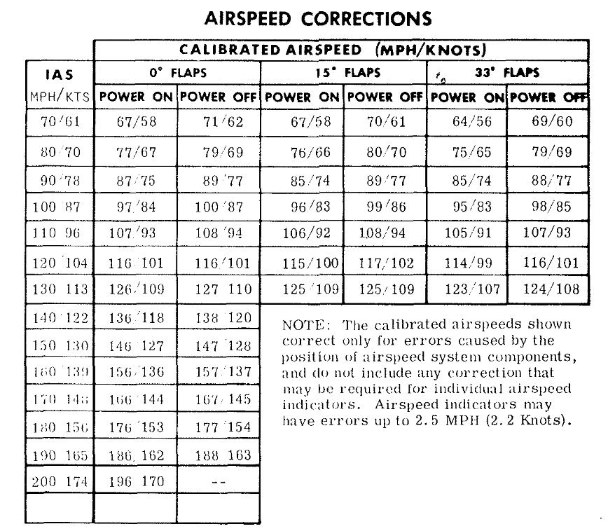
Actually, thinking about this: If you got 2 ASI’s and both are off by 2.2 kt, this will, to the naked eye, give a difference of about 5 kts.
Graham wrote:
is “out of the ballpark”
Well then, looks like I’ll have to invest in some camera equipment to show you guys how to do it
No it’s not
Mooney, you are arguing with a point which nobody has made. I can post the TB20 table too…
It’s like when I once said somewhere that the TB20 has a zero fuel range of 1300nm, somebody pointed out that the zero fuel range is actually zero (which is also correct) 
looks like I’ll have to invest in some camera equipment to show you guys how to do it
I think to achieve your numbers, the airframe maker would have to discover some new knowledge of subsonic aerodynamics.