I think the system is pretty accurate in the cruise regime as well.
In the interest of science  I opened up a standard pitot tube (had a duff heater) and here it is

The whole thing is copper. The heater seems to be a ceramic element. It is not obvious how they put it together; there may be joints I can’t see. The wavy damage is due to the milling cutter catching on the ceramic and bending the copper tube wall.
There are no special features inside after the air has arrived via the hole at the end. It then passes through a pipe of about 3mm ID, past the heater, all the way to the outlet.
Thanks for your scientific interest and this picture Peter, interesting indeed.
The ram rise heated (  ) very non-IFR pitot tube on the Panther LSA, is similar to the standard RV one. The distance of the 90° bend to the wing skin is given as a minimum of 3".

There is apparently more than one way to achieve a good position relative to the wing. I find the Luscombe pitot tube design intriguing and it’s made from a very hard aluminum alloy that doesn’t bend easily. It just pokes out of the leading edge through a grommet with no external fitting. Luscombe was very cheap.
I found it accurate and also there was no change when slipping aggressively.

I have never BTW turned on pitot heat for flight in any aircraft. The only time I’ve done so is to check if it works during annual inspection. This may something about the climate in which I generally fly and my preference for flying in good weather
Silvaire wrote:
This may something about the climate in which I generally fly and my preference for flying in good weather
Or that you don’t fly IFR…
Or that you don’t fly IFR…
Also very much to do with climate and preference for good weather I would think
This got me thinking about the BOM from Levil

It has alt, ASI and AOA from air data on the BOM itself. It’s not obvious how where these probes are, particularly not the static and AOA. The total probe is probably at the tip. Does anyone have one of these?
The BOM can sense AoA and yaw with differential pressure across the four static ports around the cone of the tip. It is similar to the AIMMS probe:
https://aventech.com/products/aimms30.html
I have tested and approved the AIMMS 10, 20 and 30 probes on a number of airplanes. They are very precise – but more costly than most GA applications would accept.
I was researching a bit a while ago and found this. A neat experiment as I find.
Using the way a barometric sensor in smartphones works as a pitot:
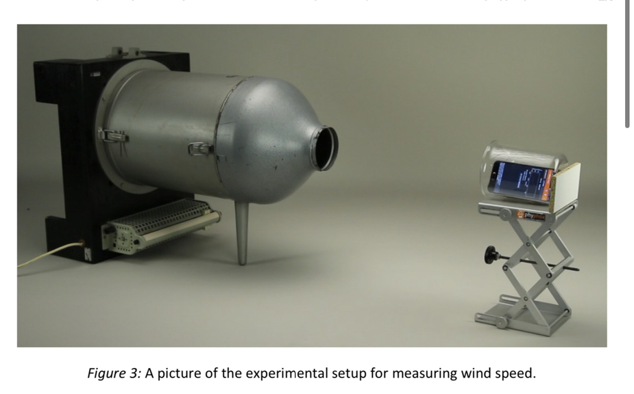
They then went on to buy a sensor chip and connect it to an actual pitot tube (there are some for RC aircraft for ~€10). Using this app (Phybox, which is really cool btw.) they plottet the speed readings obtained via the pitot against gps derived ground speed (in a car) and it was perfectly accurate. Even pointing the smartphone into the moving air was accurate. So next time your pitot fails, just hold your phone out the storm window ☺️.
How is the static pressure determined?
LeSving wrote:
How is the static pressure determined?
Just an assumption: some smartphones like the iPhone have barometric sensors. This might be used? Or else you would include a static pressure probe somewhere along the tube of the device.