I’m wondering about best practice about connectors for twisted pairs (CAN) wires. It’s for the electronic compass to be placed in the wing tip. The compass needs + and – and CAN high and low. The CAN wires needs to be a twisted pair. The wing is foldable, and also detachable, and I don’t want to rewire every time I do that (it won’t be often, but from time to time). For the lights, I will use some standard connector, CPC or similar? But the CAN wire twisted pairs, how are they supposed to be connected without “breaking the twist” ? Could they also be connected with the same CPC?
Gigabit ethernet works fine with a small “broken twist” (the RJ45 plug/socket at each end). I’d have to imagine CANbus can tolerate a connector in the middle given the much slower data transmission speeds.
The twisting is not at all critical.
CANBUS is really slow. The twist is there mainly to achieve a reasonably controlled impedance (120 ohms or so) and to help ensure that interference is picked up equally on the two signal wires.
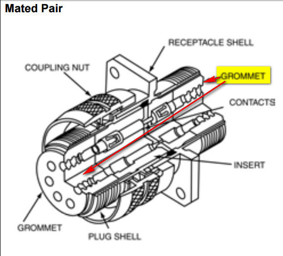
That CPC connector is OK but if it is what I think it is, it won’t achieve sealing from moisture reaching the contacts. For that you have to either use a cable with a circular outside sheath (and the connector has an o-ring at the entry) or use a connector where the individual wires pass through a rubber washer e.g. this ITT/Cannon KPT
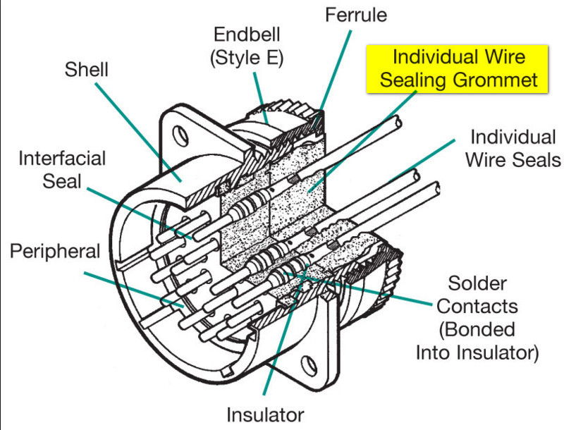
which is how most of the milspec ones work. Another example is shown on page 1 here
I would happily combine both the lighting and the CAN stuff in the same connector. Just make sure you use a shielded cable for the CAN, with the shield not used for the ground and connected securely to the airframe (metal?) at both ends, for lightning / RF etc protection.
I know nothing about electronics but the statement that the shields should be connected to the airframe at both ends and NOT used for ground is confusing me. Isn’t the airframe the ground?
(I feel sorry for anyone reading this whose first language is not English!)
The airframe of an all-metal aircraft is indeed the “ground” but it is also used as the return “wire” for all kinds of crap e.g.
and since the airframe resistance isn’t zero (especially if some connections are corroded) you will get a voltage drop between any two arbitrary spots on the airframe as a result of the above currents flowing through various bits of it.
On a “plastic” plane the situation is far worse.
That is why one should never use the airframe as the return path for anything important e.g.
Hence the fluxgate signals should not use the airframe as the ground, even though there is obviously a micro inside it so the wires carry digital (CAN) signals only. A normal King fluxgate (KG102) is analog. The Sandel one, SG102, is also digital (it uses RS422).
This takes us to the purpose of any cable shield 
It prevents the fluxgate wires picking up all kinds of radiated crap e.g.
This shield will be for the above protection only; the purpose being to conduct the crap into the airframe. That is best achieved if it is connected to the airframe at both ends, or even in more places.
The scenario where one grounds only one end of a cable shield is to do with avoiding ground loops, and is a different thing. One does that too, but I would not do it in this case.
the statement that the shields should be connected to the airframe at both ends and NOT used for ground is confusing me.
The meaning, as I take it, is that the shield must not be used to carry the return of the power current. That is to say the power to the device should start from the battery, using red wire in an automotive equivalent, through a breaker/fuse/switch, then back from the device (with a black cable of at least the same gauge) to the battery, or to a central earth point. On top of that, the shield of the data cable should be grounded, to the frame here or there, or ideally to the same central earth point. What one should not do, but is occasionally observed, is to use the shield/braid of the data cable as the power return.
NB your concern for non-native speakers was much appreciated – perhaps you thought of me when adding it – but there was no need: your words couldn’t have been clearer.
@Peter: I do not think loads of kW are induced to an aircraft even when flying within metres of a radar antenna, which would be unusual to say the least. Radars do not transmit megawatts, and the fraction of their transmitted power absorbed by the plane decreases rapidly with distance.
And more @Peter: plastic aircraft are not worse at all, in this respect; they only impose the use of a central earth point, which is a good thing in any plane. They do make it a lot harder to make the plane lightning-proof, though.
Thanks, no problems using the same connector then.