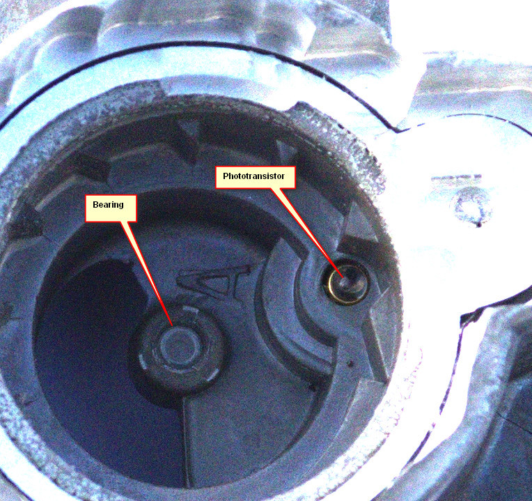
Shadin (Floscan 201) fuel flow transducer internals
I have put the one which recently failed on a milling machine and opened it up
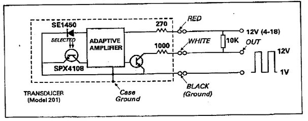
Schematic (from Floscan):
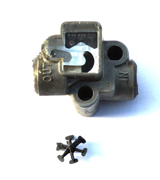
The transducer, with the plastic impeller
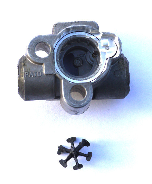
The underside
The impeller
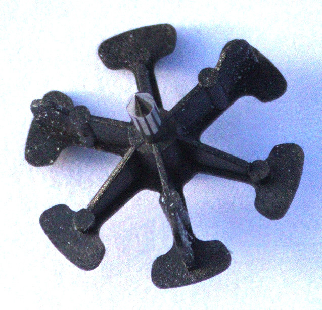
What is interesting is that the impeller is just a tiny lightweight piece of plastic.
It is also clear (as per the certification requirement) that if the impeller gets stuck, the fuel flow through the device is not affected at all.
The LED which illuminates the phototransistor was in the material which was machined away to get this pic
It makes you wonder how these devices can ever fail… my bet would be on avgas ingress into the electronics.
The very light weight of the impeller also explains why it suffers so badly from turbulence in the flow – as described here
I had one failed in my TB20 – the impeller started to slow down and at the end it just jammed showing zero flow. That seemed as great savings in fuel 
the impeller started to slow down and at the end it just jammed showing zero flow. That seemed as great savings in fuel
That’s an extremely unsafe failure mode. I wonder if there is a flow meter design that excludes this mode altogether.
Mine went to ~40 USG/hr as I lined up for takeoff (great, I thought, no need to do yet more full-of-crap exams for the bloody €ASA-mandated HPA so I can fly the Lancair Evolution TP ) and then fell down to zero and stayed there.
I aborted the takeoff, obviously, because you can never know for sure the full extent of any system failure (e.g. anything electrical could be a wire with its insulation abraded and about to short to the airframe near a fuel leak) and did a fuel system inspection before flying down to Lausanne with it
One can’t achieve 100% reliability or even a verification of the failure; well not with a simple open-collector output where there is no independent signal to check the impeller rotation. One could have two sensors on the impeller which would be good but then which is the good one? It would work only if one of them failed totally. I don’t see any way of dealing with it which, upon failure, will not require (for any pilot without a death wish, that is) a fuel system inspection.
A jammed impeller won’t block or even slightly restrict the fuel flow, which is the main thing.
Actually I doubt Emir’s impeller jammed. I think the electronics failed, as they did in mine. The impeller in mine rotated just fine – you could spin it to some astronomical RPM just by blowing into it. Also the TB20 has a 100 micron filter upstream of it.
Actually I doubt Emir’s impeller jammed. I think the electronics failed, as they did in mine.
You’re probably right. When I took it out, blowing to impeller made it spining freely.
I wonder if there is a flow meter design that excludes this mode altogether.
There are numerous ways to measure fuel flow without any moving parts at all. Many fuel injected engines (e.g. those installed on most Cessna twins) derive fuel flow from the fuel pressure measured at an injector nozzle. Then there are venturi-type flow meters, ultrasonic flow meters, wheatstone-bridge flow meters, coriolis-force flowmeters and all the other types I can’t remember now (university was 25 years ago…). Here is a manufacturer who makes all sorts of flow meters for large aircraft: http://www.badgermeter.com/Flow-Instrumentation/Cox-Turbine-Meters/Industries/Aerospace-and-Aviation.htm
But obviously very few manufacturers went through the process of certifying their sensors for light aircraft so we are stuck with two or three approved models.
Fuel pressure is the proxy used for flow on most injected GA planes’ fuel flow gauges. The fuel distributor has a line coming out of it which goes to the gauge
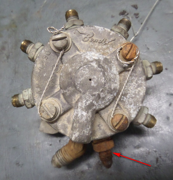
(that one is not mine, thankfully )
But it’s no good for a totaliser, which needs a ~1% accuracy.
Coriolis gives you mass flow, but while fuel mass flow is what actually makes the engine make X HP, arguably one wants to measure volume because that is what the fuel tanks are
But if Shadin (Floscan actually – these parts are made for boats and processed by a 145 firm to be sold for GA at 3-6x the price) have problems making a LED + phototransistor circuit less than reliable, all bets are off… That already has zero moving parts. Maybe there is a general issue with transients (capacitively/magnetically coupled starter motor spikes, etc) which gradually damage the gain of the transistor(s)? In that case there should be protection components, but I bet there aren’t.
What is really interesting is that in the above link, Floscan sell them directly

No wonder Shadin dropped the price from ~$600 to $333.
But it’s no good for a totaliser, which needs a ~1% accuracy.
The Cessna 421 (the Cessna twin I am most familiar with) fuel totalisers are fed from the same pressure measurements that drive the flow needles and I never had any accuracy problems with them. It’s probably a matter of the pressure transducer calibration and some linearisation done on the raw values.
…but while fuel mass flow is what actually makes the engine make X HP, arguably one wants to measure volume because that is what the fuel tanks are.
Almost everything I have flown with either more than one engine or turbine powerplant(s) has it’s fuel gages indicating “lbs” (mass). All the relevant tables in the manuals are for fuel mass as well. Makes M&B calculations easier because you don’t have to convert fuel volume to mass.
One fuel system specialist in the USA has just told me that above about 11 USG/hr the flow distributor is wide open and the fuel distribution is determined by the head loss in the thin pipes leading to the injectors, and the injectors themselves.
In a 421C (GTSIO-550, IIRC) the flow will obviously be well above 11GPH most of the time. So any linearisation would be fairly tricky to do if fuel pressure only was used, but obviously anything is possible if you throw enough effort at it.
In a 421C (GTSIO-550, IIRC) the flow will obviously be well above 11GPH
GTSIO-520 Typical fuel flow during cruise is 100lb/hr (per engine) and 250lb/hr (per engine again) during takeoff. So yes, well above 11Gal/hr. But obvoiusly they found a way to get accurate values from these flow figures. The totaliser was always spot on (+/- 20lb).