I had copied the engine dehumidifier Achim described here almost immediately after the post appeared. I used silica gel that changes color once it is water saturated. However, I was never really sure when that would be and how well it really worked. Moreover, I found replacing the silica gel really annoying and therefore I thought about a maintenance-free solution for quite a while.
I used the long time without our plane to make something better. First of all I wanted to know how the setup I had actually performed. I bought an Arduino board and a few temperature/humidity sensors and fabricated a measurement chamber using a little food container I bought at the local supermarket. Good news is that it worked quite well. I found that relative humidity was reduced from about 50% to 20%. I wasn’t patient enough to run experiments under different conditions and for a longer time, I had another idea anyway.
It’s probably sufficient to pump reasonably dry air through the engine and it has to be avoided that water condensates inside the engine. It appears to be an obvious solution to make the water condense before the air enters the engine i.e. dry the air by cooling it down with a Peltier element.
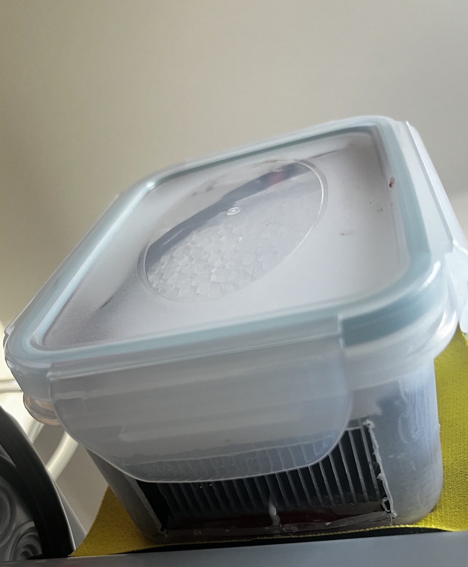
I continued on the food container way and the device now looks like someone has spilled his lunch bag.
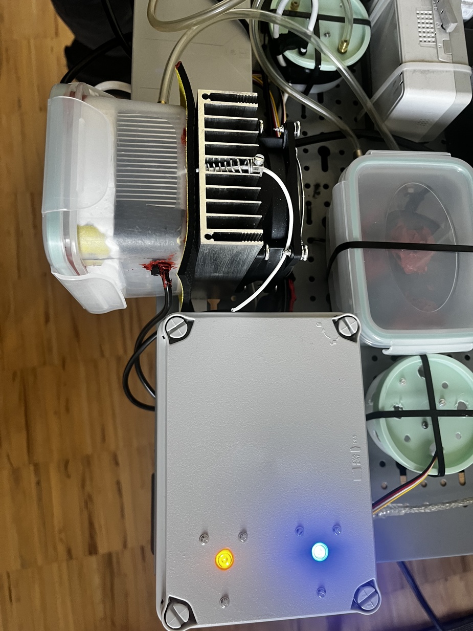
No lunch inside 😉
The principle is dead simple: Air flows through a chamber where it is cooled down, through a pump, a measurement chamber and then into the engine.
The aquarium pump does 50 liters per hour. Unfortunately it has no hose nozzle on the input side, therefore I had to put it in one of the food containers as well. It’s held in place by a few dollops of RTV. I attached a heat sink to either side of the Peltier element, separated by some silicone foam. While the hot side has a fan, the cold side is also enclosed in a food container that is cut open accordingly. There is a large opening at the bottom end where the air enters and condensate can flow out. I used some styrofoam and silicone as baffles to make sure the air gets sufficient contact to the heat sink.
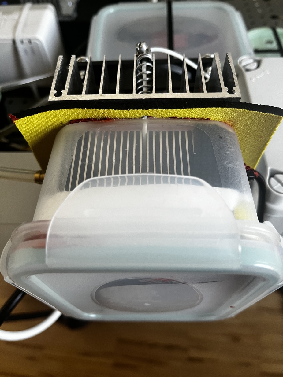
Cooler, top view
Air enters, water drips down through this cut out
In total there are two temperature sensors and two combined temperature/humidity sensors.
One of the temp sensors is attached to heat sink on the cold side of the Peltier element. To avoid that the heat sink on the cold side of the Peltier element ices up, I control the power by one of the PWM outputs of the Arduino and a little MOS FET module.
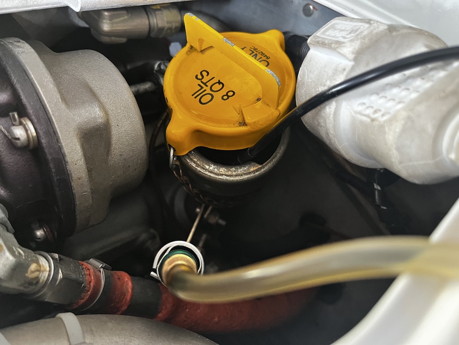
The other temp sensor is soldered to a longer cable and is attached to the hose that delivers the dry air to the engine. With our engine the dipstick has a separate receptacle from the filler neck. I found a hose that fits the dipstick receptacle perfectly, so the dry air goes in there. I insert the temp sensor into the filler neck to get the accurate temperature inside the engine. I’ll have to make a replacement for the filler neck cover, maybe I’ll have it 3D printed.
One of the temp/humi sensors measures the ambient air, while the other measures the air that goes to the engine.
The temperature of the heat sink on the cold side of the Peltier is PID controlled with a set point of one degree Celsius.
With the 50 liters/hour air flow the Peltier element can hold its one degree set point up to around 24 or 25 degrees ambient temperature. Above that, the PWM duty cycle reaches 100%. As long as one degree set point can be reached, the dew point of the air going to the engine is about three degrees, therefore I guess that the air is cooled to three degrees at average.
The colder it gets, the poorer is the performance of the system. While at 22C/55%rel. ambient the output is 35%rel., it is 39%rel. at 15C/60%rel. ambient. At 11C/66%rel. ambient the output is 45%rel.
To avoid condensation inside the engine, the Arduino stops the pump if the engine temperature gets too close to the dew point of the output air, ambient temperature is too low or output humidity is too high. It resumes operation once the conditions change.
In case you’re interested you can find the software here. It’s written in C++ (well, Arduino style C++). The main loop, basic I/O and setup is implemented in EDH.ino, while the state machine that controls the pump is in edhSM.[h/cpp] The software came to life as a data logger (to assess the performance of my old dehumidifier). In the beginning I thought I would need to log six values every five minutes, precision reduced to eight bits. The AtMega I use has only 4096 bytes of eeprom what would give me about 2 days and eight hours if I stored uncompressed data. This appeared a bit short to me and I therefore implemented a simple compression algorithm which generate 128 byte records. I use a simple Kalman filter to reduce the noise and then calculate delta-delta values which are compressed mainly using a simple-8b method. This way size is reduced to about one quarter so I can store about ten days in 5 minute intervals. It would be easily possible to increase this using RLE but then I would lose a lot of data which is not yet stored when power is turned off. Of course this could be mitigated by a staged approach, but I don’t see too much benefit. Don’t look at the implementation of this too closely, it was meant to be just a prototype… For the Kalman filters and the PID control I use Arduino libraries.
In the current implementation I persist the average temperature and humidity values reduced to eight bits precision, except for the cooler temp, which I reduce to four bits and store the state of the main state machine in the remaining four bits.
The whole setup is mounted on a frame that resides on the wing of the aircraft while it sits in the hangar. Besides the dehumidifier there is a trickle charger (BatteryMinder) and a GSM switch used to turn on the engine preheat mounted on the frame.
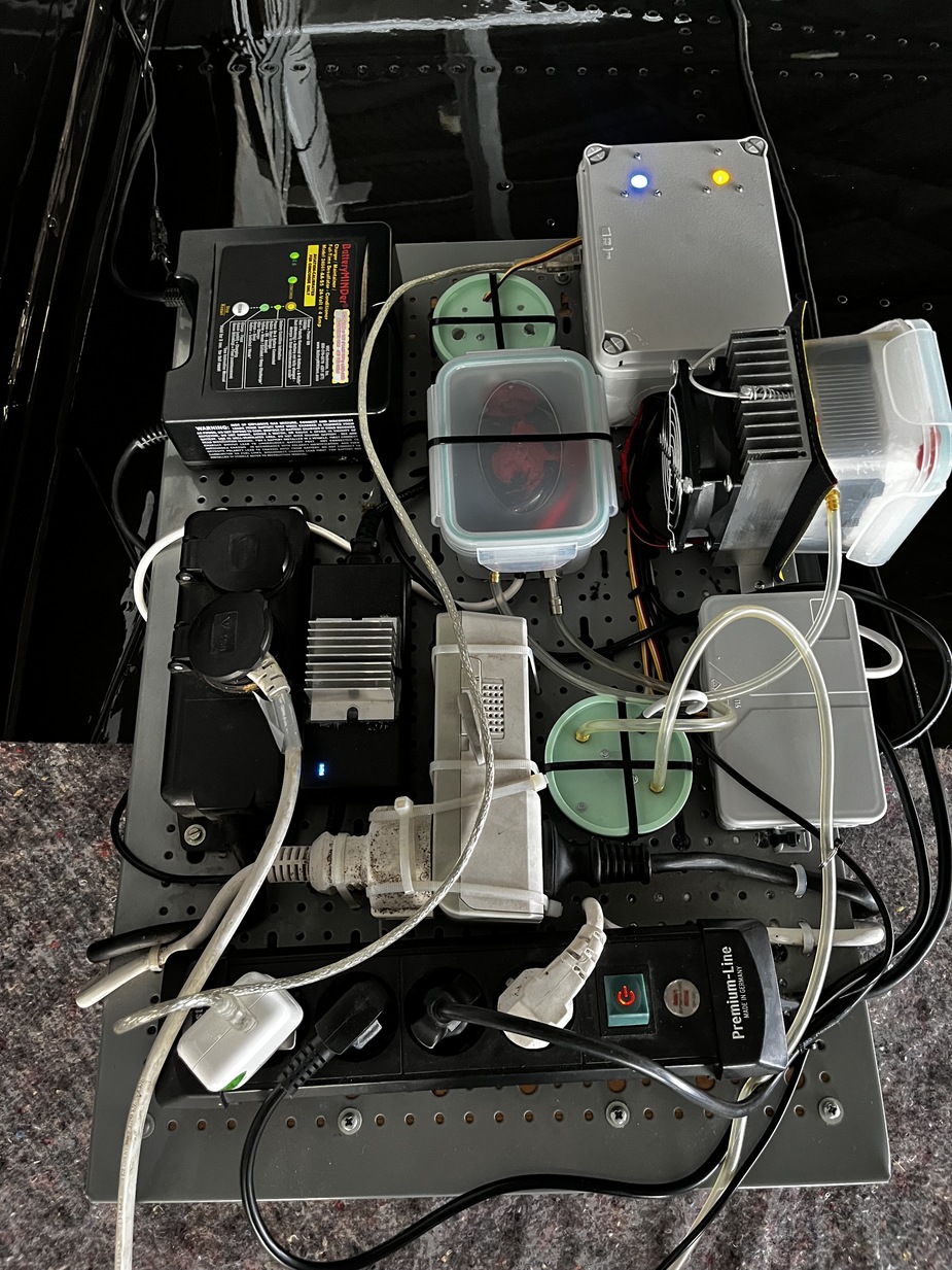
The “ground support unit” on the wing
Very cool! Similar concept to the Black Max engine dryer, but yours has a lot more technology.
That’s some serious stuff  Very cool. What we do in Norway is a simple electric engine heater and a blanket over the cowling
This is really impressive – many thanks for posting it.
What I was not able to see is how you get the dry air into the engine. What I see is a cockpit dehumidifier. For drying out an engine one would use the oil dipstick hole, or the exhaust. Or maybe something attached to the air intake.
It’s an engine dehumidifier, see the pictures below:

The first one shows the hose and the cable of the temperature sensor.
The second one shows the hose that is in place of the dipstick and the temperature sensor that goes into the filler neck. I’ll have a cover 3D printed where the sensor cable goes through, but I haven’t drawn it yet.
The white extension cord is for the Reiff engine preheat.
The little Peltier element and the aquarium pump wouldn’t be able to dry the cabin, I think.
I think to blow air into an engine you need a well airtight fitting, because the dry air has to leak past the piston rings and all kinds of other stuff. So I would get a screw-in dipstick fitting, or something which snugly fits onto the exhaust (but might be worse because the exhaust system is full of leaky bits so might not work so well).
I started building something similar (not as slick as yours) years ago but never finished it
Great system! I need something similar to stop recharging my silica gel cartridges…need to give it some thought!
Thx for sharing!
I suspect the biggest problem for most people will be the ability to bring mains power to their plane.
If you can do that, there are loads of commercial products which squirt out standard aircon air i.e. 50% RH. And it may be possible to tweak them to go lower.
The hose that supplies dry air to the engine fits absolutely airtight. Just the temperature sensor doesn’t yet but I’ll change that.
I suspect the biggest problem for most people will be the ability to bring mains power to their plane.
Luckily (for us 🙂) that’s not that common around here. Almost all people here have mains power in their hangars.
If you can do that, there are loads of commercial products which squirt out standard aircon air i.e. 50% RH.
Yes, but that wouldn’t be as much fun 😀
Very nice set-up, thanks for sharing!
As Peter alluded to, I guess the goal would be to keep the whole engine dry, not just the crankcase. How do you make sure the dry air doesn’t just blow out the breather and never reaches the combustion chambers?
On the most pragmatic way to keep the engine dry, I did my brainstorming on my own and here is my current thinking (My plane sits in an unclimatized and unheated hangar)
I bought a boot dryer from Amazon, it has 4 outlet hoses. It produces about 50*C warm air, and given its a commercial product to be used in houses, fire hazard should be minimal. Draws about 350w power.
Planning to connect 1 to the cabin air to keep moisture out of the cabin. 2 would go to the engine below the cowl. Cowl covered with a blanket. The last hose connected to the oil dipstick/filler. Would maybe tie off the breather and measure airflow through the exhaust.
I guess if I keep it running non stop, it would do the trick. But 350w is considerable. Also the dryer is maybe not built for nonstop use.
So instead I bought a WiFi connected smart plug. I would assume the relative humidity in the hangar is highest in the early morning hours when the air is the coldest. But total water content of the air should be lowest at that time, too. Therefore, I would set up the following cycle: don’t run at all during Daylight (relative humidity dropping due to heating up of air). After sunset, run 5 minutes every half hour. Early morning, run 10 minutes every half hour. Again, given that I put low water content air in the engine in the early morning, the relative humidity of that air should reduce as the plane heats up during the day. So no running required during the day.
I bought some remote thermometer/hygrometers in order to track temp and humidity below the cowling, and might as well put one in the exhaust. Just to track effectiveness.
What do the experts here think about my master plan?