Peter wrote:
I have a feeling that either my TC is over-reading or the AI is under-reading the roll angle, by 1-2 degrees.
Is it the same for both turn directions?
Yes it is.
Getting back to this, I remain puzzled as to where the roll angle is configured in the KFC225.
There are no less than three places where “config” is done:
 )
)Method #1 definitely doesn’t support the roll angle config. I’ve been all around the menus there.
Method #2 supports these items and not apparently anything to do with the absolute roll angle value.
Method #3 is this but it seems to apply only to offsets i.e. zero errors.
Does anyone know where the absolute value of the roll angle is set?
The KI256 has been changed a few times (for unrelated reasons) and the KC225 likewise. On the face of it, one could achieve a greater roll angle just by attenuating the roll output from the KI256, but that will also reduce the loop gain.
It sort of matters because an aircraft turning onto a localiser at 18 degrees will generally overshoot it and then has to work its way back to the centreline. One can tweak it by flying slower, say 100kt instead of 130kt, but one doesn’t always want to do that.
Absolute bank angle limit is set as part of the certification data and can’t be adjusted in the field. The data is stored in the config module. Bendix-King used to supply the certification file on a floppy but I haven’t touched one for years so don’t know how it’s delivered nowadays.
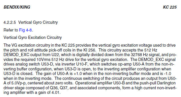
1.5.4 KCM 100 CONFIGURATION MODULE
The KCM 100 Configuration Module is a nonvolatile memory that is used to store the certification
gains, installation options and adjustments, as well as the error log for a KFC 225 system installation.
OK; thank you.
I am aware of that config module (it is a little box containing a 10p 93c46 or similar EEPROM ) and know that some of the things one sets up in the above mentioned three config modes end up stored in there. Not all; some get stored in an EEPROM in the autopilot computer. And the two side pots don’t get stored anywhere, which is stupid (they should have been digital adjustments).
I never managed to get my hands on a KFC225 certification diskette (a 3.5" disk) either, although I do have some others.
However the certification data was never changed. It just happened, at some point I don’t recall but several years ago, that the roll angle changed from 22-23 degrees to 17-18 degrees.
It may have been a change of the KC225 computer; that was done a few times, but IIRC that never changed this angle (and it shouldn’t, of course). Well, a too-high LVDT excitation output from the KC225 would cause this problem too but I have checked this with a scope.
It may have been a change of the KI256 (they need an overhaul every 2-3 years) but again that doesn’t make sense. Well, if you had a KI256 which has too-high a roll output, that would have exactly this effect, but I’ve changed the KI256 several times during the duration of this issue, and most of the replacements were freshly overhauled by a top US shop. The shop knows exactly what is involved: the KI256 output is 50mV/degree of pitch or roll and they test that.
So I would be surprised if this was a certification data issue. It’s a mystery.
I am wondering if one of the two side pots might be it. They are ambiguously described in the IM. I think one of them is basically a roll axis gain. But that isn’t the same thing as a roll angle limit which I believe is implemented in software.
I am beginning to think that the cause behind this reduced roll rate (16deg on today’s flight) is something to do with the KI256 overhaul process, which uses a King-documented fixture and at 400Hz. Whereas the KC225 emits 512Hz. The LVDT transformer in the KI256 should not be ratio-affected by this but you never know what is in the test fixture.
The reason for the suspicion is this which was partly fixed by replacing the static tubing with much better quality (but same ID) stuff than the Socata original tubing, but it is still there in a very small way.
If the KI256 had too much output, you would get exactly this effect on roll, and you would get control loop instability (oscillation) on pitch too.
The KC225 having too much excitation output would explain it too, but it can’t really output more than the 10V RMS spec – not possible within the 15V supply rails:
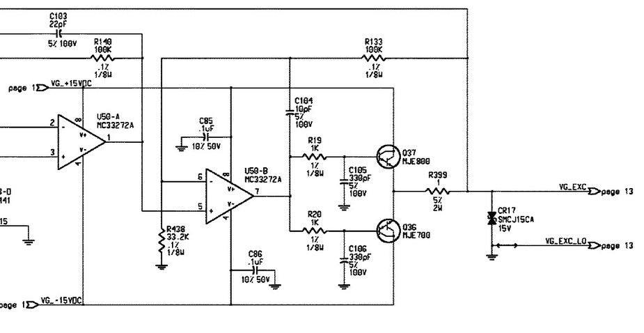
No comment on the use of 0.1% resistors there… muppet circuit design, and no wonder avionics cost so much.
I am reading this with much interest as my airplane is doing the same exact thing, albeit with KI-256 married to a KFC 200 auto-pilot.
The bank angles are supposed to be maxing out approx. 20-22 degrees during large heading changes commanded (I have been told) and I am getting about 18 degrees in both directions just like Peter here. My TC also strangely shows pretty much a standard rate but when I time the turn it is clearly slightly less (longer) than standard rate (although contributing effect to this is the fact that the A/P rolls in and out of the bank/turn quite gently so when timing the turn you lose few seconds at the beginning and end).
I am learning to live with it. When capturing the VTF for example, it does not overshoot IF you use the A/P the correct way (arm the APR mode and use the HDG for the A/P to intercept the VTF course at which point ARM indication will change to CPL and the A/P figures out the bank angle without any overhoot or oscillation all the way to MAP). Note that this is for A/P WITHOUT GPSS.
I think one could tweak the roll angle by adding a resistor to the KI256 roll output wires. That would attenuate the signal, making the autopilot think more roll is needed.
18 degrees “works” but you get overshoots on LOC intercepts unless you fly quite slowly.
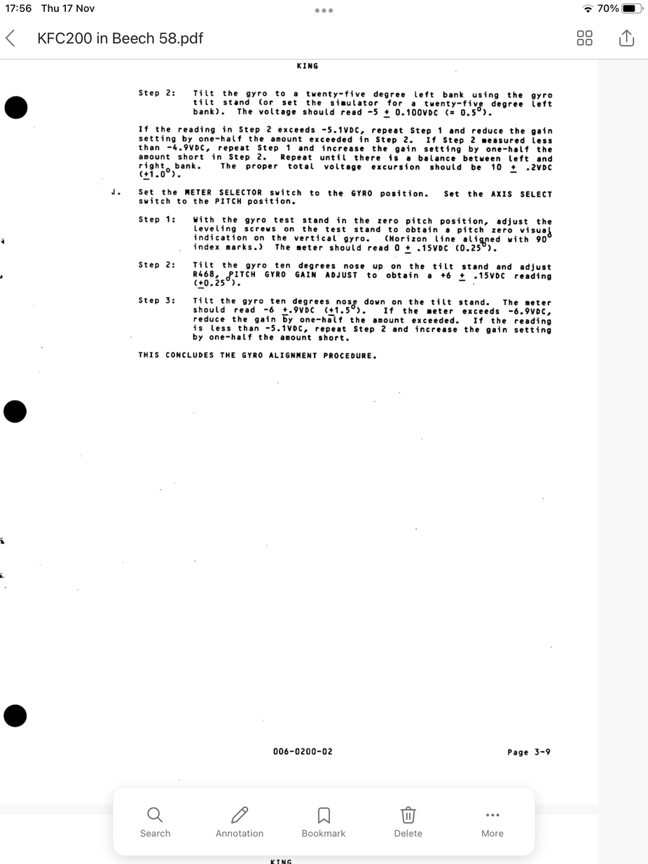
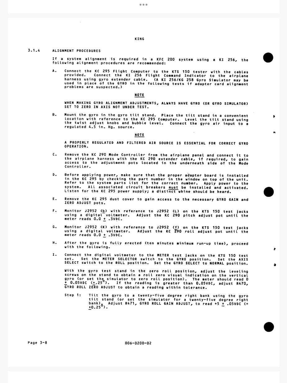
There is a calibration procedure for the KFC200 to match it to the KI256 and check the bank angle scaling – similar to that used with the KFC225:
PM me if you want to complete manual and include a personal e-mail address.
I have a bit of trouble relating the above to the KC225. That has two pots on the side (so needs the $2000 bus extender, which I have) but IIRC they are just pitch and roll nulls.
There is another “problem”:
I happen to know that a Castleberry electric version of the KI256 (TSOd but no STC) has been tested and produced the full 23 degrees roll angle, with the same KC225 on which a Castleberry-overhauled KI256 produces only 18 degrees. I think the most likely explanation is that the KI256 overhaul is being tested at 400Hz (the KI256 MM) while the KC225 uses 510Hz (IIRC) and the LVDT pickoff coils on the KI256 should produce more output at 510Hz than at 400Hz, which would make sense.
I have no idea what frequency a KFC200 uses for the KI256 excitation.
That alignment platform (which King dealers were supposed to buy, for some large amount) is a PITA because you need a vac pump and a long KI256 extension cable. In 2008 I visited a company which had it  but I doubt anybody else in the UK (or most of Europe) has got this. So a solution needs to be found which can be tweaked in-flight. And that bus extender is not usable in flight either – it is way too flimsy.
Your problem is obvously not fixable by adjusting the roll nulls. The gyro roll gain adjust as hinted by @wigglyamp is what you need.
When in similar circumstances and in the absense of complex test equipment, your A&P may find it acceptable to do some minor blind ground adjustment then go fly in VMC, verify and repeat until satisfied.