In the above diagram you see hose #13 which connects into the static pipework of the aircraft.
Also this is in the IM
One weird possibility is that there is water in the pipes which shifts around when you turn.
So it’s own port but not its own source/line.
I must check if alternate static also applies to it. Don’t know how it works.
Water is weird… but why not.
Maybe there is somewhere with my static line to sort out.
Loads of possibility then….
If only I had the possibility to perform those inspections with the help of a mechanic, by myself, in a heated hangar :-)
Alt static will apply to it, I am sure.
Water is common, as are bugs (live and dead).
Also pipes pinched by stuff, even by control linkages  I know one owner who collected his plane from a famous German company with a pinched static line, and I collected my plane from a famous UK company with control linkages cutting into a cable harness… so anything is possible.
Yes… the hangar where one can work Lack of these is what keeps the maintenance business in business, at many places. And a heated hangar is absolute luxury.
Once again, Peter is right
Alternate air will actually apply to the AP static source.
This test may be significant in my case.
182 STATIC LINE MAP
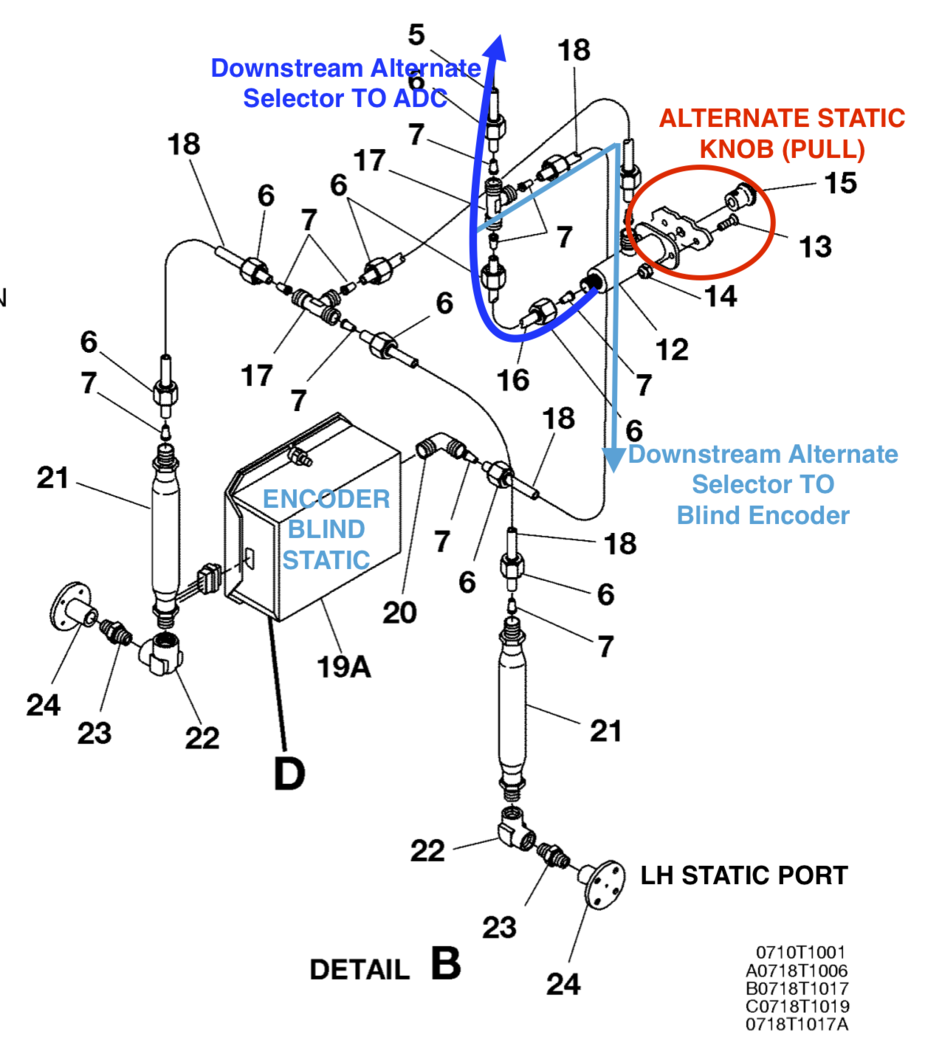
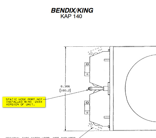
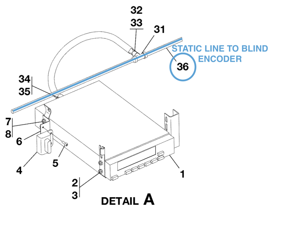
KAP 140 STATIC LINE CONNECTION (please refer to color code)
EDIT: reading again the post and my problem, unstable VS during TURN, I wonder if my main problem is not around imbalanced static input. I guess this is where I should start, and ALTERNATE STATIC will obviously help…
New datas…
During steady climbs (and descents), constant heading and turns (L and R), it appeared that:
When I have the time, I will post some video.
On the previous one, I think that the VS oscillation was to be linked with updraughts at low level with some terrain not far…
My actual conclusion is that ACC calibration mainly solved the problem.
However, i may send the pitch servo to a solid workshop for bench test during next annual. It can’t do arm, and will allow to check the trim sensor in it.
It’s quite easy to check the KS271C servos, with a very simple wire harness. I think I posted the wiring here previously. 28V power, a switch to supply 28V to the clutch, and you open the black plastic case and waggle the motor+gearbox assembly while measuring the -3V to +3V torque output.
Very often the strain gauge assembly is broken. The is a design defect in that they allow too much bending (too much strain) on the steel cantilever, and this causes the strain gauges to become unglued. One can glue them back on – it’s only epoxy.
If anyone has burnt out servos of this type, I am very interested. I collected a few in the past, all declared “beyond economic repair”. The servo assembly can be transplated out of those, in a few minutes. No calibration of the gauge amplifier is likely to be required.