I flew the Dubrovnik LDDU ILS twice in the past week and could swear that it is really narrow.
When flying an ILS, I set up the GPS in the OBS mode, with the runway bearing, so I have a reference for where to expect the localiser. On the LDDU one, it doesn’t start to move until the very last bit before the full intercept.
We need to know what sensitivity the GPS was on (ENR, TERM, 0.3) and, if ENR whether it’s SBAS or not.
This is flying the ILS, not flying the GPS track.
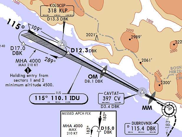
Here is the plate:
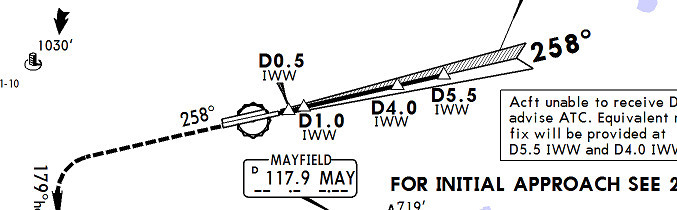
and this is EGKK – angle looks same
I had a quick look in ICAO Annex 14. The localiser should have a specified width at the threshold (or at a particular distance before the threshold if the runway is short). Since the transmitter is located at the far runway end the localiser must have a different angular width depending on runway length. Also there are reasonably large tolerances (±17% for a CAT I localiser).
Peter wrote:
I set up the GPS in the OBS mode, with the runway bearing, so I have a reference for where to expect the localiser. On the LDDU one, it doesn’t start to move until the very last bit before the full intercept.
Peter wrote:
This is flying the ILS, not flying the GPS track.
If you express surprise at how late into that FSD the ILS starts to move, you need to know three things, the sensitivity of the GPS, the range from the ILS aerial and the accuracy with which you set the OBS.
The FSD of the GPS in OBS mode is clearly relevant, as it could be anything from 0.3nm to 5nm, a scale factor of 17.
The range is obviously relevant, as the FSD will be on tramlines – the same at 1nm from the ILS aerials as at 20nm, a scale factor or 20.
The accuracy of the OBS is relevant, because the FSD of the ILS needle is 2.5°. Who is to say whether the QDM is 114.5 or 115.5? That’s a whole degree in 2.5, another scale factor of 2.
Multiply up those scale factors and you get to 680. 
OK, a bit artificial, but you get my point?
I don’t, because the GPS FSD setting is irrelevant.
In OBS mode, I just use it in this scenario to get a magenta line on the MFD. I am not looking at anything to do with the GPS track deviation. I am flying purely on the ILS receiver (as one should be when flying an ILS). FWIW, my GPS is always set to 1nm FSD when enroute or flying non-RNAV approaches.
It is however a fair point that there might be an error in the OBS setting of the GPS. The KLN94 has an installer adjustment for this and it should be right, and this image doesn’t suggest it is out:
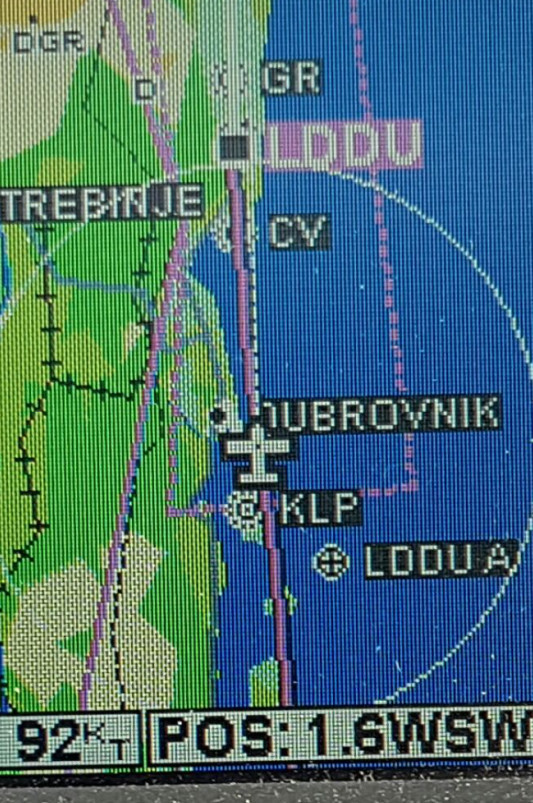
That circle is 10nm radius, BTW.
This pic (a zoomed-in crop) doesn’t suggest my ILS receiver (KX155A driving the KFC225 via decoded analogue) is off, either.
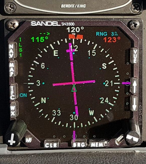
and the Sandel SN3500 (which gets the composite lateral deviation from the KX155A and decodes it internally using DSP) agrees
I have obviously missed your point.
I thought that it was a matter of how nearly centred the GPS OBS has to be to get a non-FSD indication on the ILS?
That is a question about the ratio between ILS FSD and GPS FSD. If the GPS FSD is 1nm, and the ILS the normal 2.5°, then you would expect them to overlay at 24nm. At 12nm, the ILS should move off the stops at half scale on the GPS and at 6nm at quarter scale.
If that is the case, then I hold that all three questions are relevant.
The GPS in this case just generates that magenta line. That line will always lie in the same place on the map, for a given OBS setting (115 in this case).
Peter wrote:
The GPS in this case just generates that magenta line. That line will always lie in the same place on the map, for a given OBS setting (115 in this case).
Then I am confused by how you are measuring the crosstrack error in order to determine whether the width of the ILS beam is “normal”? Just from the map scale?
It comes back to what I said above; you would expect the ILS to start moving at ½nm at 12nm and ¼nm at 6nm. That is comparable with the width of your magenta line in your moving map above, which, taken with the ±½° error, means that turning onto the localiser by using the magenta OBS line alone is bound to throw up anomalies.
The short answer is no.
The longer answer -
The regulations are that the Course Signal (the bit that titivates your CDI needle) shall give maximum scale deflection when at a point 105m abeam the ILS Reference Point (the ILS Reference Point is a point vertically above the intersection of the ILS centreline and runway threshold). Consequently, using a bit of trigonometry and assuming that the localiser is at the upwind threshold, one can see that a Course Signals width on a 4448m runway (Dubai International 30L) will be 2.7 degress (Inv Tan 105/4448)* 2. On a 1820m runway this angle would be 6.6 degrees (Inv Tan 105/1820)*2. However, the regulations state that the maximum allowable angle shall be 6 degrees. Consequently, in cases such as Biggin Hill, the system is setup so that maximum deflection shall happen at Point B which is 1050m from the threshold. In other words, you simulate that Biggin Hill’s runway is 2870m long.
How does this manifest itself? If you’re making an approach to a really long runway your needle will not come alive until a lot later than you expect. Conversely, if you’re positioning for an ILS at a short runway, the needle will come alive far earlier. Duibrovnik’s ILS Loc should be about 3.64 degrees wide.