That is a wonderful attitude and a great job that you are doing.
The only additional advise I would supply is: always factor engine movement in its mounts and wiring slack and service loops for this reason as well as future routing changes whenever able.
AC43-13-1B ch’s 8 and 11 are your friends too.
Flyingfish wrote:
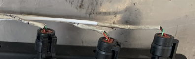
Miles of unshielded low power cables tightly mixed with the “big boys” did not sound like a great idea to me… Thoughts
That is a good idea, but I never experienced such issues with my EI monitor whose thermocouple and FF turbine wiring inevitably run next to alternator main output wire. I cannot say the same thing of the variable-resistor temp sensors on my DAVTRON intercooler indicator, but fortunately those run far away.
Flyingfish wrote:
u-shaped (open) aluminum tube attached and to a pair of cylinder head cover screws and grounded
That is a complex way of fixing the issue. If the U is the right way up, it will also accumulate crud at the lower end. You’d also need to flare inlet and exit to avoid damaging wiring. This has been used as a way to encapsulate ignition wiring on radial and big old engines. No matter how much effor t you put into your design, you may have to change it later. I use fibreglass sleeving This gives you much more flexibility in different senses. It is somewhat conductive and provides a minor measure of shielding. If you are really interested then there are also full EMI shielding versions available. You can install it in such a way that it is also easy to replace if it gets ‘oiled-up’.
Last, now you have a clean engine compartment you should try and keep it as clean as possible. I know: these TSIO engines will never be 100% clean, but the closer you are the easier to identify any minor leaks in the future: better to know where your oil is coming from.
A big big thank you Antonio. Your support and advice are much appreciated.
You are very welcome! We are looking forward to pics of your gorgeous new engine!
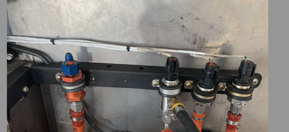
That looks amazingly clean.
Except for the tightly bent wires coming out of those sensors or pressure switches
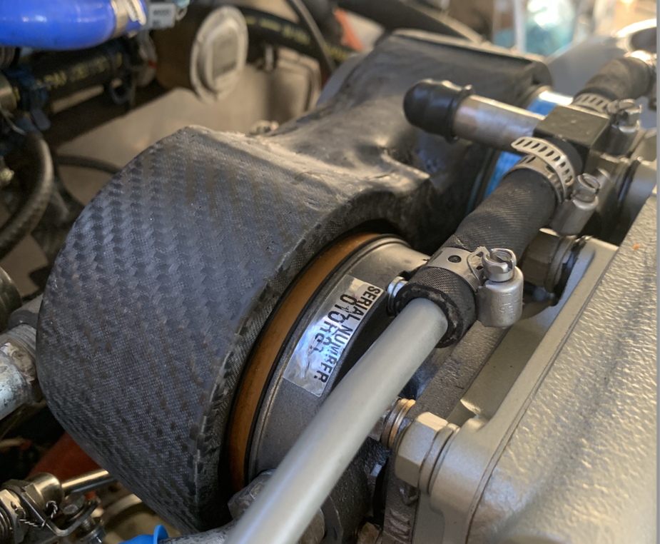
What is that black thing around the two vacuum pumps? A cooling shroud?
Well observed Peter 😁
These are not yet properly secured, I just pulled the loom out of sight for the photo ;-) and you caught me!
There’s one more sensor coming and the check valve is moving to the right, following the latest test fit …
The shroud is indeed for cooling the air pumps.
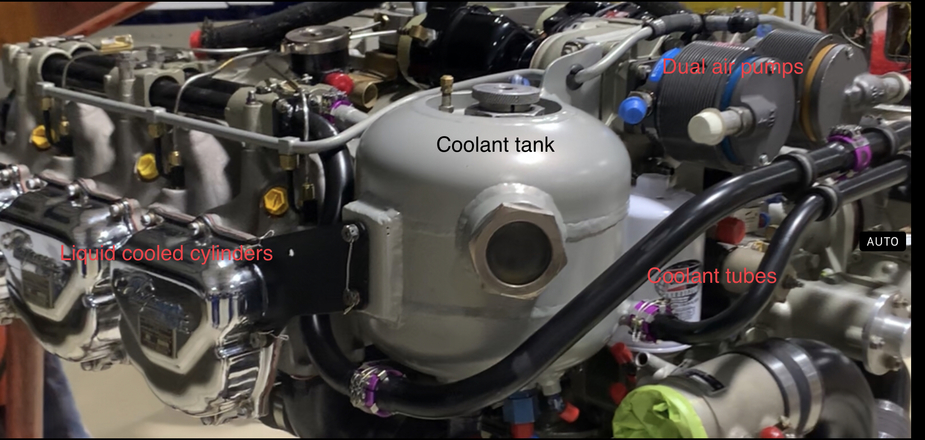
This is the beautiful job that LOMA Air returned. While the initial mandate was IRAN (inspect and repair as necessary), we ended up with a brand new crankcase and a long list of items that essentially turned this into a “pragmatic rebuild”. My technical contact at LOMA air, Dietrich, gave us friendly, very wise advice and I am overall very happy with LOMA air’s service.
Knowing that there was one unproven cylinder, I did not want to run the risk of finding an early failure after the engine was installed. so LOMA Air did a 10 hour test run on my request. Dietrich reported a very smooth running engine and a whopping 307 HP of output with no turbo installed.
I checked the chart, and it looks like this is a lot more than what the turbocharged engine should deliver at the same MP of 29.5 inches.
So I do expect this to be a very powerful engine, guessing 375+ HP at full power (39.5 inches) . Am I correct ?
If I can get the cooling right, take-off and climb should be quite interesting.
This engine’s turbo is enormous.
Frankly I think they over did it: since the POH restricts the pilot from using all of the available MP over FL200, there is no benefit from making so much pressure.
I think they should have resized the turbo for a critical altitude of FL200. This would have saved weight ( the aircraft is very nose heavy) with no performance penalty.
One very valuable “discovery” during the reassembly process was that the “cold “ side of the turbo can be freely rotated. In my previous installation, the outlet (with its silicon duct) had been twisted to be dangerously close to the exhaust. We were frying silicon at an alarming rate!
I did not know this could be twisted back to safety, and none of my previous mechanics suggested it. So here you go:
you can twist your turbo’s output away from harm’s way !!!
This is the optimised cabin air setup after many iterations. The two mixers are assembled together and installed directly at the cabin air check valve. There are only 3 ducts left: one from the bleed air side and two to/from the forward mounted cabin air cooler.
On this photo, you can see one of the Bowden cables before it was pacified and safely clamped in place.
Before I get nailed again: this was just a test fit, the final assembly has proper bolts everywhere and an aluminum bracket taking the g-loads to the engine mount 😉
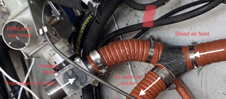
This mod saves weight, bulk, chafing risks and improves comfort during high altitude cruise because the lukewarm bleed air is no longer cooled by an unnecessary path in the subzero zones of the cowling. It was the kick start of the cleanup process – a very rewarding journey, as each duct we could remove, shorten or relax opened the way for the next move.
I did not have a paperwork issue because under FAA rules this is a minor mod, simply relocating the existing system out of harm’s way.
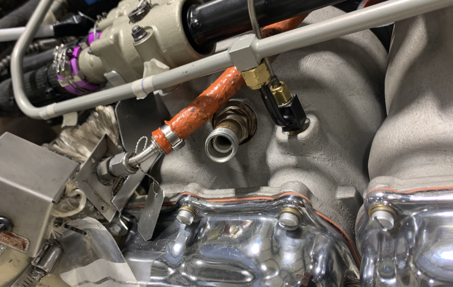
This photo shows how we maintained easy access for placement and removal of the oil filter. No tubes or ducts allowed here!
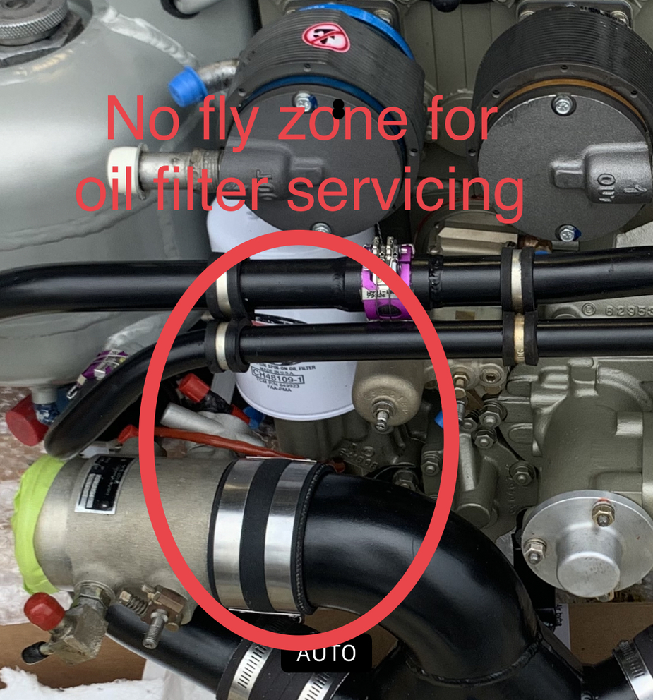
The photo is a bit misleading – there is plenty of room for the part to pass. The thin-walled aluminum coolant tubes have meanwhile been wrapped to protect them from chafing and tool impact.
Working under the supervision of a friendly mechanic (thank you Alain 👍) helps a lot with this kind of ideas.
The E400 is notorious for being a maintenance nightmare, and these little touches come a long way in helping cut the inefficiency out.
Another area where I expect a benefit from the cleanup is the intercooler’ s exhaust side. In the factory setup, used cooling air was simply dumped in a crowded region of the cowl, making its way down to the exits without any positive guidance.
So there’s another « no fly zone » planned there. I am hoping to have enough room for at least partial ducting towards the low pressure areas. We’ll see…